Understanding a bathroom plumbing diagram is essential before starting any renovation, repair, or new construction project in your home. These technical drawings show exactly where pipes, drains, and fixtures need to be positioned, saving you thousands of dollars in costly mistakes and rework.
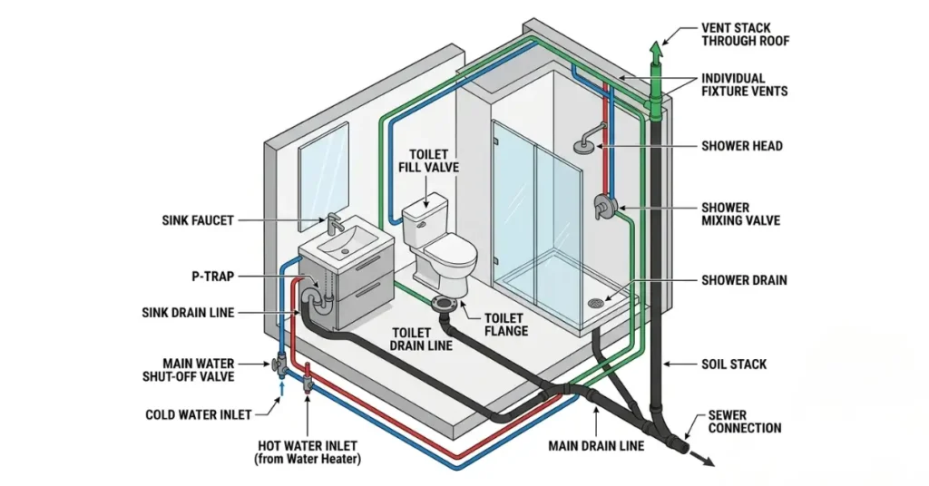
A bathroom plumbing diagram uses color-coded lines and standardized symbols to represent your complete plumbing system. Blue lines indicate cold water supply, red lines show hot water, and black lines mark drain pipes. Whether you’re working with a contractor in Phoenix or tackling a DIY project in Chicago, learning to read these diagrams helps you communicate clearly and understand exactly what work is being done in your home.
This complete guide covers every type of bathroom plumbing diagram, from rough-in measurements and drain layouts to vent configurations and fixture spacing. You’ll learn to read professional diagrams confidently and understand the International Plumbing Code (IPC) standards that keep your bathroom safe and functional.
How to Read a Bathroom Plumbing Diagram
Reading a bathroom plumbing diagram might seem complicated at first, but these drawings follow simple conventions that anyone can learn. Once you understand the basic symbols and color codes, you can interpret any professional plumbing diagram with confidence.
Every bathroom plumbing diagram uses lines of different colors and thicknesses to represent different pipe types. Cold water supply lines appear as thin blue lines running to each fixture. Hot water lines show up as thin red lines, typically running parallel to the cold lines. Drain pipes use thick black lines because they are physically larger than supply pipes. Vent pipes appear as dashed green lines extending upward through your roof.
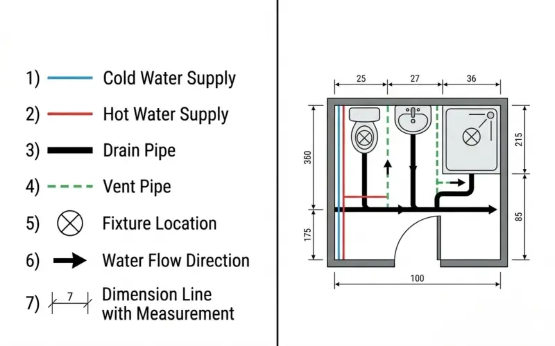
The International Plumbing Code (IPC) establishes standard symbols that plumbers and contractors use nationwide. A circle with an X inside represents a fixture location. Small arrows on pipes show the direction water flows. Dimension lines with measurements tell you exact distances between fixtures and walls. These standards mean a diagram drawn by a plumber in Los Angeles will look nearly identical to one created in Boston.
Common Plumbing Diagram Symbols
Learning the basic symbols makes reading any diagram much easier. Supply line symbols show whether pipes carry hot or cold water using color coding. Drain line symbols indicate pipe diameter with numbers like 1.5 inches for sinks, 2 inches for showers, and 3 inches for toilets. Vent symbols use dashed or dotted lines to distinguish them from solid drain pipes.
Fixture symbols represent toilets, sinks, showers, and tubs with simple shapes viewed from above. A toilet appears as an oval, a sink as a rectangle or circle, and a shower as a square with a drain symbol inside. Understanding these basic elements lets you visualize your entire bathroom plumbing system just by looking at a flat diagram.
Bathroom Plumbing Layout Diagrams
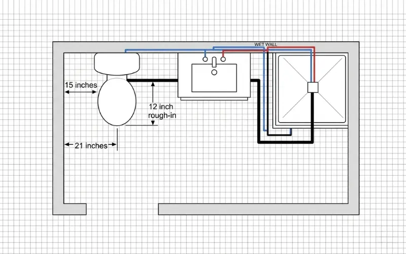
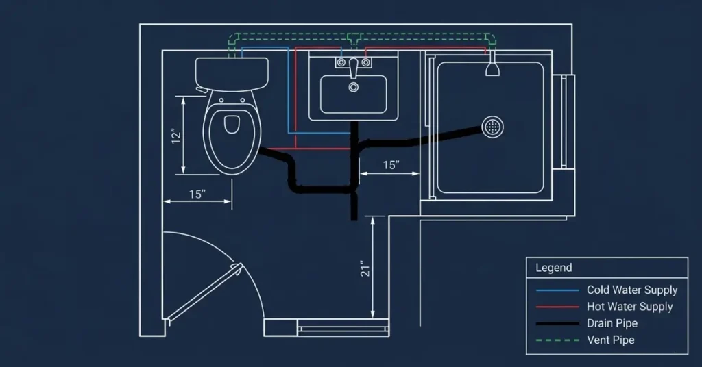
A layout bathroom plumbing diagram shows your bathroom from above, like a simple floor plan. It helps you see where the toilet, sink, shower, tub, supply lines, drains, and vents sit before any wall is opened. If you need the bigger picture first, our complete bathroom plumbing guide explains how these parts work together.
Full Bathroom vs Half Bathroom Layouts
A full bathroom layout usually includes a toilet, sink, shower, and tub, so the diagram has more drain and vent connections. A half bathroom, sometimes called a powder room, usually shows only a toilet and sink. Because fewer fixtures are involved, the drain-waste-vent system is simpler.
Fixture spacing is just as important as pipe location. The International Plumbing Code (IPC) requires at least 15 inches from the center of the toilet to a side wall or cabinet. It also requires at least 21 inches of open space in front of the toilet. These numbers are often shown with dimension lines on the drawing.
Second Floor Bathroom Considerations
A second floor bathroom plumbing diagram needs extra attention because pipes must pass safely through floor framing. Drain pipes must slope downward toward the main stack, while vent pipes rise upward to connect with the vent stack. In older homes in Boston or Chicago, tight framing can make these routes harder to plan.
A good layout also shows which wall carries most of the plumbing. This is often called the wet wall. Placing the sink, toilet, and shower near the same wet wall saves labor, reduces pipe runs, and makes repairs easier later. Good diagrams help homeowners and contractors agree on the layout before expensive construction begins. This is especially helpful when comparing a bathroom double sink plumbing diagram with a standard vanity layout.
Bathroom Plumbing Rough-In Diagrams
A bathroom plumbing diagram for rough in shows exactly where pipes must be positioned before walls and floors are finished. Getting these measurements right the first time prevents expensive teardowns and corrections after tile, drywall, or flooring is already installed.
Toilet Rough-In Specifications
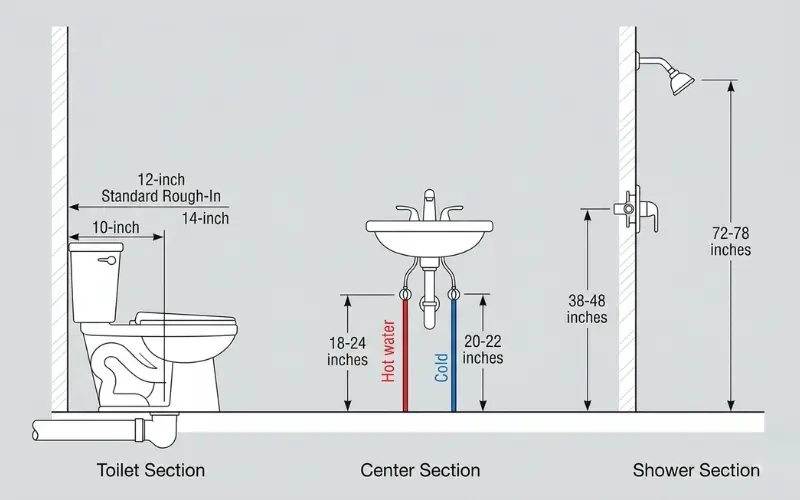
The most critical measurement on any rough-in diagram is the toilet rough-in distance. This measures from the finished wall straight out to the center of the toilet drain in the floor. Most American toilets use a standard 12-inch rough-in measurement, which has been the industry standard for decades.
However, some older homes built before 1950 in cities like Philadelphia and New York may show a 14-inch rough-in instead. Compact bathrooms sometimes use a 10-inch rough-in to save floor space. Your diagram must clearly mark this dimension because buying the wrong toilet size means it simply will not fit.
Sink and Vanity Rough-In Heights
Bathroom sink drain pipes typically center between 18 and 24 inches above the finished floor. This height gives enough room underneath for the P-trap and supply connections. Hot and cold supply lines usually rough in at 20 to 22 inches high, positioned about 4 inches apart from each other.
Wall-mounted sinks need supply lines roughed in at 30 inches above the floor to match standard faucet heights. A bathroom sink plumbing diagram shows these vertical measurements with dimension lines and arrows pointing to each connection point. For a broader look at how these measurements connect to your whole home system, our house plumbing system diagram shows how bathroom rough-in pipes tie into the main supply and drain lines throughout your entire house.
Shower rough-in diagrams mark the shower valve location between 38 and 48 inches above the finished floor. The showerhead rough-in sits at 72 to 78 inches high. Following these standard measurements from the American Society of Plumbing Engineers (ASPE) ensures your fixtures install correctly without adjustments.
Understanding Bathroom Drain Diagrams
A bathroom plumbing drain diagram shows every pipe that carries wastewater away from your fixtures. These drawings are critical during renovation because drain pipes must be sized correctly, sloped properly, and connected in the right sequence for everything to work without backing up or leaking.
Drain pipes always flow downward using gravity. The International Plumbing Code (IPC) requires a minimum slope of one-quarter inch per foot on horizontal drain pipes. This means for every 12 inches of horizontal pipe, the drain drops one-quarter inch. Too little slope causes slow drains and clogs. Too much slope causes water to run faster than solid waste, leaving debris behind inside the pipe.
Bathroom Sink Plumbing Diagrams
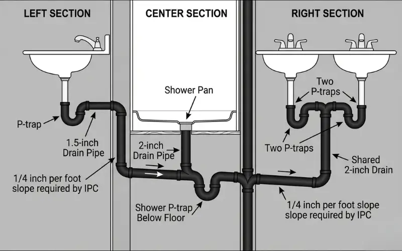
A bathroom sink plumbing diagram focuses on the P-trap connection beneath the sink basin. The P-trap connects to the tailpiece above and the trap arm below, which routes wastewater into the wall drain. The IPC requires a minimum 1.5-inch diameter drain pipe for every bathroom sink without exception.
Shower and Tub Drain Diagrams
A bathroom shower plumbing diagram shows the shower drain connecting to a 2-inch pipe beneath the shower pan. The tub drain and tub overflow connect together before joining the main branch drain. Both shower and tub drains require a P-trap positioned below the floor to maintain the water seal against sewer gases.
Double Sink Drain Configurations
A bathroom double sink plumbing diagram shows two separate P-traps connecting into a single shared drain line. Each sink needs its own P-trap before the pipes combine. This shared connection typically uses a 2-inch drain pipe instead of the standard 1.5-inch single sink pipe to handle the increased water volume.
Bathroom Plumbing Vent Diagrams Explained
[INSERT IMAGE 5 HERE]
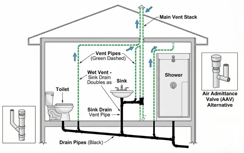
Alt Text: Bathroom vent plumbing diagram showing wet venting configuration and AAV placement
A bathroom plumbing vent diagram shows how air enters your drainage system to keep water flowing smoothly and safely. Most homeowners never think about venting until something goes wrong, like slow drains, gurgling pipes, or sewer gas smells coming up through bathroom fixtures.
Every drain in your bathroom needs a vent connection shown on the diagram. Without proper venting, the flowing wastewater creates a vacuum that literally sucks the water seal right out of your P-traps. Once that water seal is gone, sewer gases enter your bathroom freely. A properly drawn venting bathroom plumbing diagram prevents this problem by showing exactly where each vent connection must be located.
Wet Venting for Bathroom Groups
The most common venting method shown in residential bathroom diagrams is wet venting. According to IPC Chapter 9, a bathroom group consisting of a toilet, sink, and shower can share a single vent pipe using the wet venting method. The sink drain doubles as the vent pipe for the toilet and shower connections nearby, saving significant wall space and material costs.
Air Admittance Valves and Alternatives
Some bathroom vent diagrams show an air admittance valve, or AAV, instead of a traditional vent pipe running through the roof. An AAV is a small mechanical valve that opens when water drains and closes to block sewer gases. The Uniform Plumbing Code (UPC), followed in western states like California and Oregon, has stricter rules about where AAVs are permitted compared to the IPC. Always check your local building department requirements before using an AAV in your bathroom vent diagram design.
Reading Measurements on Plumbing Diagrams
A bathroom plumbing diagram with measurements tells you not just where pipes go, but exactly how far apart everything must be positioned. These dimensions are not suggestions. They are code requirements that every licensed plumber must follow to pass inspection and receive final approval from the local building department.
Measurements on plumbing diagrams use dimension lines with arrows pointing to the exact location being measured. A number sitting above or beside the line tells you the required distance in inches or feet. Center-to-center measurements show the distance between the middle of one fixture and the middle of another. Edge measurements show clearances from the outside edge of a fixture to the nearest wall or cabinet.
Standard Clearance Measurements
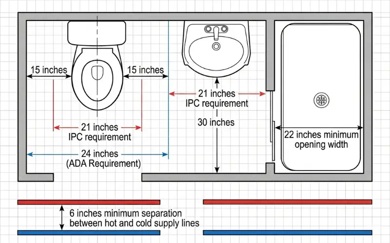
The International Plumbing Code (IPC) requires specific clearances around every bathroom fixture. The toilet needs a minimum 15 inches of clear space from its center to any side wall or cabinet. It also needs at least 21 inches of open space directly in front of the bowl. The Americans with Disabilities Act (ADA) increases that front clearance to a minimum of 24 inches for accessible bathrooms.
Bathroom sink diagrams show a minimum 30-inch clearance in front of the basin. Shower openings must be at least 22 inches wide according to IPC requirements. These measurements protect both comfort and safety for all household members.
Water Supply Layout Measurements
A water supply layout bathroom plumbing diagram shows supply line heights, valve positions, and connection distances. Hot and cold supply lines must maintain at least 6 inches of separation to prevent heat transfer between pipes. In states like Texas and Florida, local amendments sometimes add additional spacing requirements beyond standard IPC minimums to account for regional climate conditions.
Basement Bathroom Plumbing Diagrams
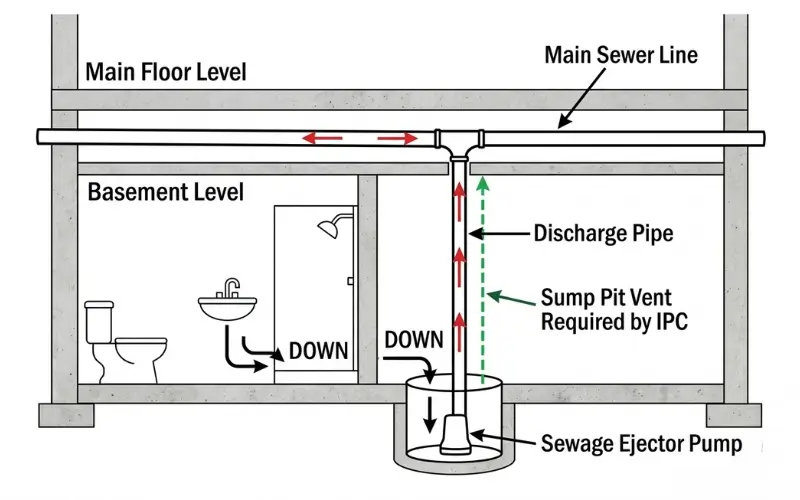
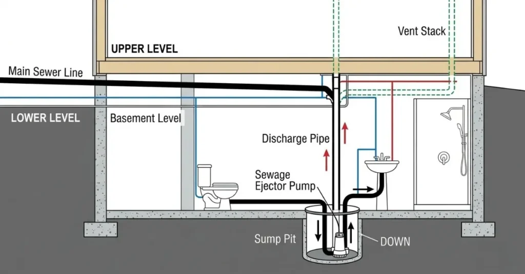
A basement bathroom plumbing diagram requires special attention because everything sits below the main sewer line. Standard gravity drainage simply does not work when your bathroom floor sits lower than the city sewer connection outside your home. This below-grade challenge makes basement diagrams more complex than standard bathroom drawings.
The most important addition on any basement bathroom plumbing diagram is the sewage ejector pump system. The diagram must show the sump pit location in the basement floor, the pump inside the pit, and the discharge pipe rising upward to connect with the main drain line above. Homeowners in basement-heavy cities like Chicago, Denver, and Philadelphia should pay close attention to these details before starting any basement bathroom project.
The International Plumbing Code (IPC) requires the ejector pump sump pit to be properly vented to prevent sewer gases from building up in your basement living space. This vent connection must appear clearly on your diagram before any contractor begins work.
For a deeper understanding of how basement bathroom systems work, our complete bathroom plumbing guide covers ejector pumps, backwater valves, and below-grade drainage in practical detail. According to HomeAdvisor, basement bathroom plumbing projects cost between $1,500 and $3,500 depending on complexity and local labor rates.
Frequently Asked Questions
What is a bathroom plumbing diagram used for?
A bathroom plumbing diagram shows the exact location of pipes, drains, vents, and fixtures before construction begins. Contractors use these drawings to position pipes correctly, pass inspections, and avoid costly mistakes during renovation or new construction projects.
What is the standard toilet rough-in measurement shown on diagrams?
Most American bathroom diagrams show a 12-inch rough-in measurement from the finished wall to the center of the toilet drain. Older homes in cities like Boston and Philadelphia sometimes show 14-inch rough-ins instead.
What do the colored lines mean on a bathroom plumbing diagram?
Blue lines represent cold water supply pipes, red lines show hot water supply pipes, black lines indicate drain pipes, and green dashed lines represent vent pipes. These color conventions follow International Plumbing Code (IPC) standards used nationwide.
Do I need a diagram before starting a bathroom renovation?
Yes. A proper bathroom plumbing diagram prevents expensive mistakes, helps contractors position pipes correctly, and is required by most local building departments before issuing permits.
What size drain pipes appear on bathroom plumbing diagrams?
Bathroom sink drains show 1.5-inch pipes, shower and tub drains show 2-inch pipes, and toilet drains show 3-inch pipes according to IPC minimum requirements.
Conclusion
Reading and understanding a bathroom plumbing diagram gives you a significant advantage before any renovation or repair project begins. From rough-in measurements and drain configurations to vent diagrams and clearance requirements, every detail on these drawings exists for a practical reason. For a complete understanding of how all these systems connect and function together, explore our detailed bathroom plumbing guide. When diagrams feel overwhelming, always work with a licensed plumber who follows International Plumbing Code standards for safe, code-compliant installations.