Most American homeowners live with a complete plumbing system running through their walls, floors, and ceilings every single day without ever truly understanding how it is laid out or how each part connects to the next. A house plumbing system diagram changes that instantly. It takes everything hidden behind drywall and beneath concrete and makes it visible, logical, and understandable in a single labeled drawing.
Understanding your home plumbing diagram is not just useful for curious homeowners. It is genuinely practical knowledge. When a plumber quotes you a repair, when you are planning a bathroom renovation, when you need to find the main shut off valve in an emergency at 2 AM in a home you just purchased in Denver or Atlanta, a basic understanding of your residential plumbing diagram tells you exactly where to look and what you are looking at.
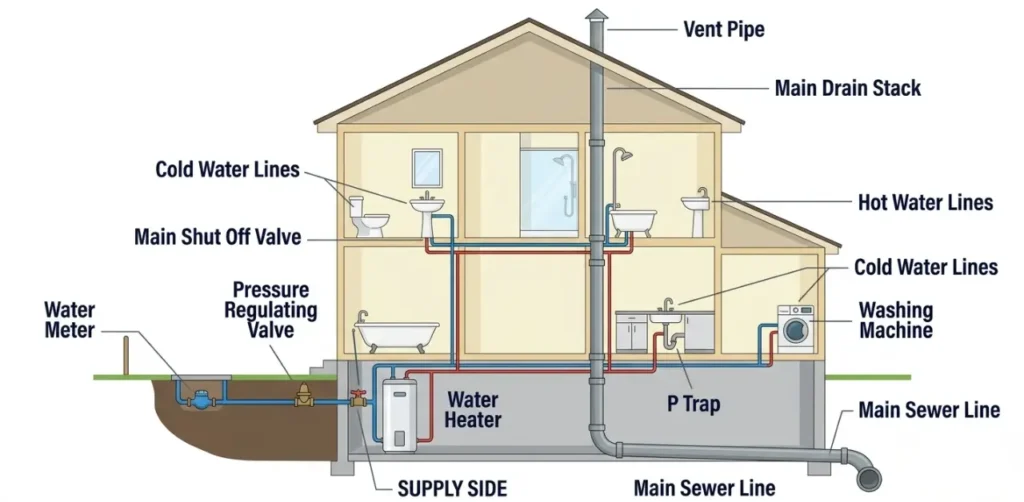
A standard house plumbing layout shows two separate systems working side by side. The water supply side brings pressurized clean water in from the municipal main through the water meter and distributes it through cold and hot water lines to every fixture in the home. The drain waste vent system carries used water and sewage out of the home through sloped drain pipes while vent pipes running upward through the roof keep the entire drainage system flowing correctly.
According to the American Society of Plumbing Engineers (ASPE), every licensed plumber in the United States is trained to read and interpret plumbing schematics before touching a single pipe. This guide gives you that same foundational understanding so you can follow along, ask the right questions, and make smarter decisions about your home plumbing system.
This guide gives you that same foundational understanding — for everything beyond diagrams read our complete plumbing systems guide.
What is a Plumbing System Diagram?
A plumbing system diagram is a technical drawing that shows every pipe, fixture, valve, and connection inside a home in a single visual layout. It maps out where water enters the building, how it travels to each fixture, and how wastewater exits through the drainage system. Think of it as a blueprint specifically for your plumbing, separate from the structural or electrical drawings of the home.
A residential plumbing diagram typically shows two systems together, the supply side and the drain side, using different line styles or colors to distinguish between them. Supply lines are usually shown in blue for cold water and red for hot water. Drain and vent lines are shown in gray or black. Plumbing schematics use standardized symbols to represent fixtures, valves, traps, and connections so any licensed plumber can read the diagram without confusion.
Most American homes built after 1970 have plumbing diagrams on file with their local building department as part of the original permit documentation. Homeowners can request a copy of their original plumbing schematic from the city or county building records office. Older homes built before permit requirements were standardized may not have formal diagrams on file, in which case a licensed plumber can create an as-built diagram by inspecting the existing system.
If you are new to home plumbing start with our complete guide on what is plumbing before learning how to read a diagram.
House Plumbing System Diagram: Main Components
Every house plumbing system diagram shows the same core components regardless of the age or size of the home. Knowing what each component looks like on a diagram and where it sits in the overall layout is the foundation of reading any residential plumbing schematic correctly.
Water Supply Side
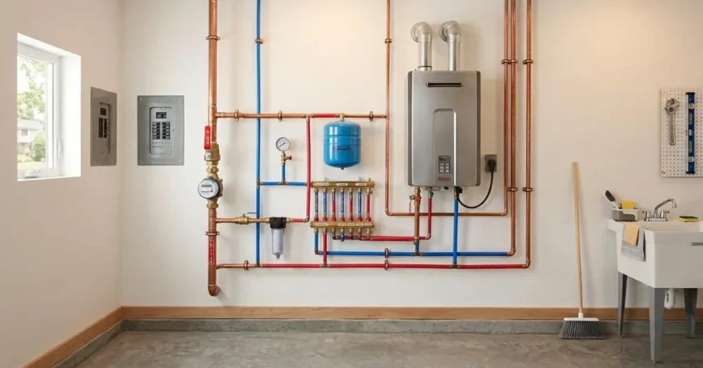
The water supply side of any house plumbing diagram starts at the water meter, which is typically shown at the property line or just inside the foundation wall. From the meter the main supply line runs into the home and passes through the main shut off valve, the single most important valve in the entire system. From there the supply line splits, cold water travels directly to every fixture while a separate branch runs to the water heater where it is heated before being distributed as hot water through red lines throughout the home.
On a correctly drawn house plumbing layout every supply line is sized and labeled according to the fixture it serves. The main supply line entering most American homes is typically a three quarter inch pipe. Individual branch lines running to sinks, toilets, and showers are usually half inch pipe. Every fixture has its own individual shut off valve shown on the diagram directly beneath or beside the fixture it controls.
Drain Waste Vent Side
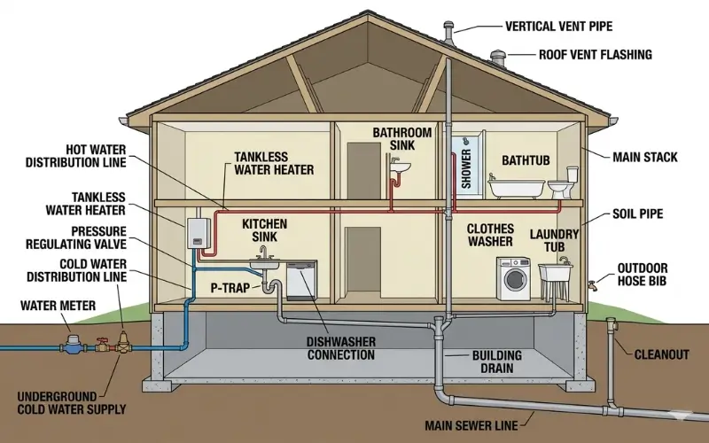
The drain waste vent side of a residential plumbing diagram shows how wastewater leaves every fixture and travels out of the home. Every sink, toilet, shower, and bathtub connects to a drain pipe that slopes downward at a precise angle toward the main drain stack, a large vertical pipe running from the basement or crawl space up through the roof. The main drain stack connects underground to the main sewer line that exits the property toward the municipal sewer system.
Every fixture on the drain side of the diagram shows a P trap, the curved pipe section that holds water and blocks sewer gases from entering the living space. Above each fixture the diagram shows a vent pipe rising vertically and connecting to the main vent stack that exits through the roof. The vent system is just as important as the drain pipes themselves and every properly drawn plumbing diagram shows both systems in full detail.
Plumbing Schematic for a House: How to Read It
A plumbing schematic for a house looks intimidating the first time you see it but follows a completely logical system once you understand the basic rules. Every line, symbol, and number on the drawing means something specific. Learning to read a plumbing schematic diagram takes less than fifteen minutes and gives you the ability to understand any licensed plumber’s work plan, renovation drawing, or repair estimate from that point forward.
Common Plumbing Diagram Symbols
Plumbing schematics use standardized symbols that appear on every residential diagram drawn in the United States. These symbols are based on standards set by the American National Standards Institute (ANSI) and the American Society of Plumbing Engineers (ASPE).
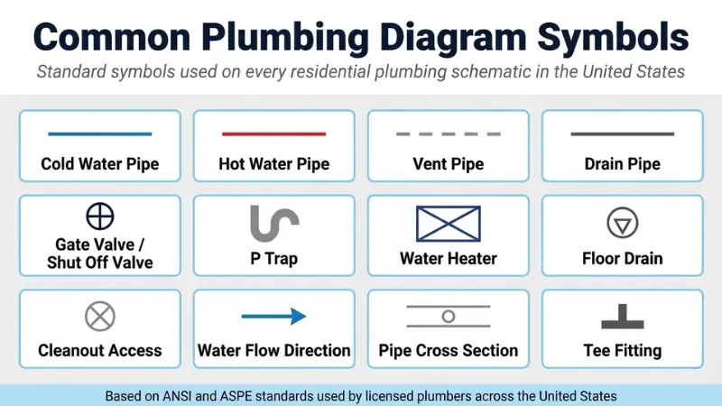
The most common symbols you will see on any house plumbing diagram include the following. A single horizontal or vertical line represents a pipe run. Two parallel lines represent a pipe shown in the cross section. A small circle with a cross through it represents a gate valve or shut off valve. A triangle pointing downward represents a floor drain. The letter P followed by a curved line represents a P trap beneath a fixture. A rectangle with an X through it represents a water heater. Arrows on supply lines show the direction of water flow through the system.
Cold water supply lines are always shown in blue on color coded diagrams. Hot water supply lines are shown in red. Drain and waste pipes are shown in gray or black. Vent pipes are typically shown as dashed lines to distinguish them from solid drain pipes on the same drawing.
How to Interpret Supply Lines
Reading the supply side of a plumbing schematic starts at the water meter symbol near the property line. Follow the main supply line as it enters the home and traces through the pressure regulating valve and main shut off valve before branching out to individual fixtures. Each branch line on the schematic is labeled with its pipe diameter, typically written as three quarter inch for main runs and half inch for individual fixture branches.
When a supply line splits into a hot and cold branch the diagram shows this clearly with the line changing color or being labeled H for hot and C for cold. The hot water branch always routes to the water heater first before continuing to the fixtures it serves. Rough plumbing dimensions are shown on the schematic as measurements from the finished wall or floor to the center of each pipe, giving plumbers the exact location to place each pipe during new construction or renovation.
Plumbing Blueprints: What They Show
Plumbing blueprints are the official technical drawings submitted to a local building department before any new plumbing installation or major renovation work begins in the United States. They are more detailed and precise than a basic plumbing diagram and carry legal weight. A licensed plumber must follow the approved blueprint exactly or risk failing the required plumbing inspection that follows the work.
A standard set of plumbing blueprints for an American home includes several separate drawings. The floor plan view shows every fixture location, pipe run, and valve position from above as if you were looking straight down through the ceiling. The isometric view shows the entire plumbing system in three dimensions, giving a clearer picture of how supply and drain pipes travel through multiple floors and walls. The detailed drawings show specific connections and assemblies at enlarged scale so there is no ambiguity about how individual components connect.
Rough In Plumbing Diagram
The rough plumbing diagram is the most practically useful blueprint for any homeowner doing a renovation. It shows the exact location of every pipe, drain, and supply connection before the walls and floors are closed in. Rough dimensions on the diagram tell a plumber precisely where to place each pipe relative to the finished wall surface so that fixtures like toilets, sinks, and showers align perfectly once installation is complete.
In most American cities including Houston, Phoenix, and Charlotte a rough plumbing inspection is required before walls can be closed. The inspector compares the actual installed pipes against the approved rough in plumbing diagram to verify that everything matches before construction continues. Homeowners planning a bathroom addition or kitchen remodel should always request a copy of the rough diagram from their plumbing contractor before work begins so they have a permanent record of where every pipe is located inside their finished walls.
House Water Supply Diagram Explained
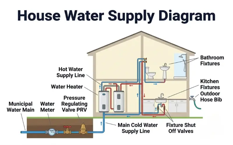
The water supply side of a house plumbing diagram shows exactly how clean pressurized water enters your home and travels to every fixture and appliance that needs it. Understanding this half of the diagram gives you the ability to trace any supply line problem back to its source, identify which valve controls which fixture, and understand why low water pressure affects some parts of the home but not others.
Cold Water Supply Lines
On any house water supply diagram the cold water system is the simpler of the two sides. Water enters the home from the municipal main underground, passes through the water meter at the property line, and enters the home through the main supply pipe. The first component shown after the meter on most American residential diagrams is the pressure regulating valve, which reduces incoming municipal pressure to the safe residential range of 40 to 80 PSI recommended by the American Water Works Association (AWWA).
From the PRV the main cold water supply line runs through the home distributing cold water directly to every fixture. The diagram shows individual branch lines splitting off the main line to serve each bathroom, kitchen, laundry room, and outdoor hose bib. In homes across cities like Seattle, Denver, and Nashville the cold water supply diagram also shows a whole house water softener or filtration system installed on the main line between the meter and the first branch.
Every cold water branch line on the diagram terminates at a fixture shut off valve located directly beneath or beside the fixture it serves. These individual shut off valves are shown as small valve symbols on the diagram and allow a homeowner or plumber to cut water to a single fixture without shutting off the entire house.
Hot Water Supply Lines
The hot water side of a house plumbing diagram branches off from the cold water main at the water heater. Cold water feeds into the bottom of the water heater through the cold inlet connection shown on the left side of the heater symbol. Heated water exits from the top through the hot outlet connection on the right side and travels through separate red lines to every hot water fixture in the home.
The hot water supply diagram shows the distance each hot water line travels from the water heater to the fixtures it serves. In larger American homes across states like Texas, Florida, and California hot water lines travel long distances from a centrally located water heater to distant bathrooms, which is why hot water takes longer to arrive at fixtures far from the heater. Some residential diagrams show a hot water recirculation loop, a dedicated return line that keeps hot water continuously circulating so it arrives instantly at every fixture regardless of distance.
Drain Waste Vent Diagram Explained
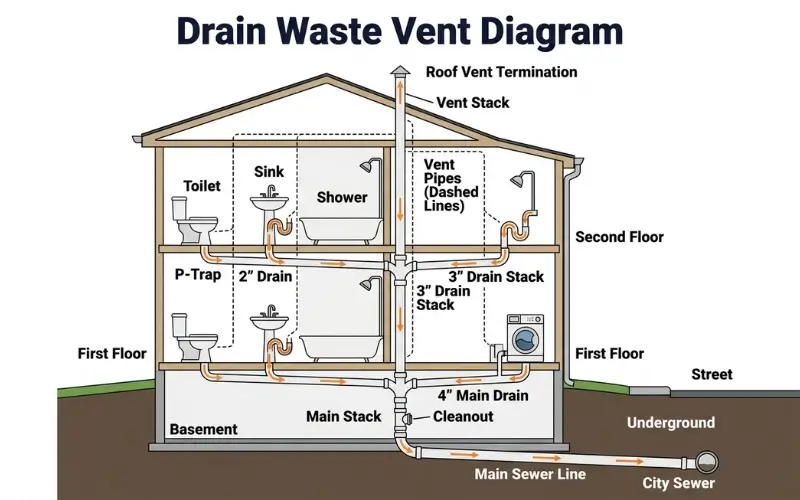
The drain waste vent side of a house plumbing diagram is the half most homeowners understand least and the half that causes the most confusion during repairs and renovations. Unlike the supply side which works on pressure, the drain waste vent system works entirely on gravity and air pressure balance. Every line, angle, and connection shown on the drain waste vent diagram exists for a specific reason and changing any one of them without understanding the system can cause drain problems throughout the entire home.
Drain Pipes and P Traps
On a drain waste vent diagram every fixture connects to the system through a drain pipe that slopes consistently downward toward the main drain stack. The International Plumbing Code requires residential drain pipes to slope at a minimum of one quarter inch per foot to maintain proper flow without allowing solids to settle and block the line. This slope requirement is shown on the diagram as a percentage or fraction beside each drain pipe run.
Directly below every fixture on the diagram sits the P trap symbol, the curved pipe section that holds a small amount of standing water at all times. This water seal is the only barrier between the living space and the sewer gas environment inside the drain pipes. Every sink, shower, bathtub, and floor drain in an American home requires its own P trap by code. The diagram shows P traps as curved lines beneath each fixture and any missing P trap on a diagram submitted for permit review will be flagged immediately by a building inspector in cities like Chicago, Los Angeles, and Miami.
All individual drain lines shown on the diagram connect to branch drain lines which in turn connect to the main drain stack, a large vertical pipe usually three to four inches in diameter running vertically through the center of the home from the top floor down to the basement or crawl space. The main stack connects underground to the main sewer line that exits the property toward the municipal sewer system or private septic tank.
Plumbing Vent Schematic
The vent portion of a drain waste vent diagram is shown as a separate set of lines running upward from the drain pipes through the walls and exiting through the roof. Every plumbing vent schematic shows how individual vent pipes connect to the main vent stack and how the main stack exits above the roofline to release sewer gases safely into the outdoor air.
The International Association of Plumbing and Mechanical Officials (IAPMO) sets the standards for vent pipe sizing and placement that every residential plumbing schematic in the United States must follow. Individual fixture vents are typically one and a half to two inches in diameter. The main vent stack is typically three to four inches in diameter matching the main drain stack it serves.
A properly drawn plumbing vent schematic also shows cleanout access points, threaded plug fittings installed at key locations in the drain line that allow a plumber to insert an auger or inspection camera without dismantling the pipe. Cleanouts are shown as small circles with a cross through them on the diagram and are required by code at the base of every main drain stack and at every major direction change in the drain line. Homeowners in older neighborhoods across cities like Detroit, Baltimore, and Cleveland should confirm that their home plumbing diagram shows accessible cleanouts before scheduling any drain cleaning service.
Single Story House Plumbing Diagram
A single story house plumbing diagram is simpler than a multi story layout but has its own specific challenges that affect how pipes are routed and where key components are placed. In a single story home all plumbing fixtures sit on one level which means every drain pipe must reach the main sewer line without the benefit of vertical drop from upper floors. This makes proper drain slope even more critical in single story construction than in two or three story homes.
The supply side of a single story house plumbing diagram typically shows a short direct run from the meter and PRV to a centrally located water heater. From the water heater both hot and cold supply lines branch out horizontally through the walls and under the floor to reach bathrooms, kitchen, laundry, and outdoor fixtures. Because all fixtures sit on the same level the supply lines in a single story diagram tend to run longer horizontal distances than in multi story homes, which is why water pressure management is especially important in large single story ranch homes common across states like Texas, Arizona, and Florida.
The drain side of a single story plumbing diagram varies significantly depending on whether the home sits on a slab foundation or a crawl space foundation. Homes built on a concrete slab, which is extremely common across the southern United States in states like Georgia, Louisiana, and South Carolina, have all drain pipes embedded inside or beneath the concrete before the slab is poured. Homes built over a crawl space show drain pipes suspended beneath the floor joists on the plumbing diagram, running with the required downward slope toward the main drain stack and sewer exit. These pipes are accessible for inspection and repair from the crawl space below, making the plumbing system far more serviceable than a slab installation.
Understanding your single story layout also helps you quickly identify the most common plumbing problems that affect ground level pipes and slab foundations.
Plumbing System Layout: Room by Room
Every room in an American home that uses water has its own section of the overall plumbing system layout. Understanding how each room connects to the main supply and drain systems helps you read any house plumbing diagram quickly and accurately.
Bathroom Plumbing Layout
A bathroom plumbing layout on a diagram shows three fixtures clustered close together, toilet, sink, and shower or bathtub. Grouping fixtures together is intentional. Shorter pipe runs reduce installation cost and make the drain lines easier to vent properly. The toilet has the largest drain line at three to four inches. The sink and shower share smaller two inch drain lines that connect to a shared branch line before reaching the main stack. Each fixture shows its own P trap and individual shut off valves on the supply side. For a complete breakdown of bathroom plumbing read our dedicated bathroom plumbing guide.
Kitchen Plumbing Layout
A kitchen plumbing layout is more complex than a bathroom because it serves multiple appliances beyond just the sink. The diagram shows cold and hot supply lines running to the kitchen faucet, a separate cold water line to the refrigerator ice maker, and a dedicated drain line for the dishwasher connecting into the sink drain above the P trap. The garbage disposal sits between the sink drain and the P trap on the diagram, intercepting food waste before it enters the drain line. For a complete kitchen plumbing breakdown read our dedicated kitchen plumbing guide.
How to Draw a House Plumbing Diagram
Drawing a basic house plumbing diagram does not require professional drafting skills. Homeowners create simple plumbing diagrams for insurance documentation, renovation planning, and emergency reference all the time using nothing more than graph paper and a pencil.
Start by sketching the floor plan of your home from above. Mark every room that contains plumbing fixtures, bathrooms, kitchen, laundry room, and utility spaces. Place each fixture in its approximate location using standard plumbing symbols. Mark the location of the main shut off valve, water meter, and water heater. Draw blue lines showing cold water supply runs from the meter to each fixture. Draw red lines showing hot water runs from the water heater to each hot water fixture. Draw gray lines showing drain pipes running from each fixture toward the main drain stack with arrows indicating the direction of flow.
For a more detailed and code compliant plumbing schematic most American homeowners hire a licensed plumber or a plumbing designer to produce the official drawings. Software tools like AutoCAD, SmartDraw, and Plumbing CAD allow professionals to produce precisely scaled diagrams that meet the submission requirements of local building departments across the United States. Free online tools like Lucidchart and Canva offer basic plumbing diagram templates that homeowners can use to create simple reference drawings for personal use without any technical training.
Frequently Asked Questions About House Plumbing System Diagrams
How do you read a plumbing system diagram?
Reading a plumbing system diagram starts with identifying the two separate systems shown on the drawing. The supply side shows water coming in, represented by blue lines for cold water and red lines for hot water running from the water meter through the pressure regulating valve and water heater to every fixture. The drain waste vent side shows water going out, represented by gray or black lines sloping downward from each fixture toward the main drain stack and sewer line. Once you identify which lines belong to which system, follow each line from its starting point to its endpoint and note every valve, trap, and connection symbol along the way.
What does a house plumbing system diagram show?
A house plumbing system diagram shows the complete layout of every pipe, fixture, valve, trap, and connection inside the home. It shows where water enters through the meter, how it distributes through cold and hot supply lines to every fixture, where each fixture drains through its P trap into the drain system, how drain pipes connect to the main stack, and how vent pipes exit through the roof. A complete diagram gives any licensed plumber a full picture of the system without opening a single wall.
What is a plumbing schematic?
A plumbing schematic is a simplified technical drawing that shows the relationships between plumbing components using standardized symbols rather than realistic illustrations. Unlike a detailed blueprint that shows exact measurements and scaled pipe locations, a schematic focuses on showing how components connect and how water flows through the system. Plumbing schematics are commonly used during the planning and design phase of a new construction or renovation project before full blueprints are produced.
How do you interpret common symbols on a residential plumbing diagram?
The most important symbols on any residential plumbing diagram follow standards set by the American National Standards Institute (ANSI). A single line represents a pipe run. A small circle with a cross represents a gate valve or shut off valve. A curved U shape represents a P trap. A rectangle with an X through it represents a water heater. A circle with a triangle represents a floor drain. Arrows on supply lines show water flow direction. Numbers beside pipe runs indicate pipe diameter in inches. Once you memorize these core symbols you can read any standard residential plumbing diagram produced in the United States.
How do I draw a basic plumbing diagram for my house?
Start with a simple floor plan sketch showing every room that contains plumbing. Mark fixture locations using standard symbols, draw blue lines for cold supply runs and red lines for hot supply runs from the water heater, and draw gray lines for drain pipes sloping toward the main stack. For personal reference this level of detail is usually sufficient. For permit submissions or renovation planning, hire a licensed plumber or use professional software like AutoCAD or SmartDraw to produce a code compliant drawing that meets local building department requirements.
What symbols are used in plumbing diagrams?
Standard plumbing diagram symbols used across the United States include single lines for pipe runs, valve symbols for shut off and gate valves, curved lines for P traps, rectangles for water heaters and tanks, circles for floor drains and cleanouts, dashed lines for vent pipes, and arrows for flow direction. Color coding adds another layer of information with blue indicating cold water, red indicating hot water, and gray or black indicating drain and waste lines. These symbols are standardized by ANSI and ASPE so any licensed plumber anywhere in the country can read a diagram produced by any other plumber.
Final Thoughts
A house plumbing system diagram turns the invisible into the understandable. Every pipe, valve, trap, and connection that runs silently through your walls and floors has a location, a purpose, and a place on the diagram. Homeowners who understand their plumbing layout make faster decisions during emergencies, ask better questions during repairs, and spend less money when renovation time comes.
Keep a copy of your home plumbing diagram somewhere accessible. If your home does not have one on file, ask a licensed plumber to create an as-built diagram during their next service visit. At Clever Pro Plumbing, we believe every American homeowner deserves to understand the system they depend on every single day.